SPECIAL FEATURE: WELDING EQUIPMENT AND CONSUMABLES
3 . M A K E S U R E A L L O F Y O U R
C O N N E C T I O N S A R E S O U N D
B E F O R E G E T T I N G S TA R T E D
Before you start welding, make sure all of your
connections are tight — from the front of the MIG
gun to the power pin attaching it to the power
source. Also, be certain there is no spatter buildup
on your consumables and that you have a ground
cable as close to the workspace as possible.
Whenever possible, hook the ground cable on
the weldment. If that is not possible, hook it to a
bench. But remember: The closer it is to the arc,
the better. If you have a questionable ground, it
can cause the gun to overheat, impacting contact
tip life and weld quality.
In addition, regularly clean any shavings from
the welding wire or debris that collects on your
consumable parts and in your liner using clean
compressed air.
4 . S E L E C T T H E P R O P E R D R I V E
R O L L A N D T E N S I O N S E T T I N G
T O E F F E C T I V E LY F E E D W I R E
Improper drive roll selection and tension setting
can lead to poor wire feeding. Consider the size
and type of wire being used and match it to the
correct drive roll.
Since flux-cored wire is softer, due to the flux
inside and the tubular design, it requires a knurled
drive roll that has teeth to grab the wire and to
help push it through. However, knurled drive rolls
should not be used with solid wire because the
teeth will cause shavings to break off the wire,
leading to clogs in the liner that create resistance
as the wire feeds. In this case, use V-grove or
U-groove drive rolls instead.
Set the proper drive roll tension by releasing the
drive rolls. Then increase the tension while feeding
the wire into your gloved hand until the tension is
one half-turn past wire slippage.
Always keep the gun as straight as possible to
avoid kinking in the cable that could lead to poor
wire feeding.
5 . U S E T H E C O R R E C T
C O N TA C T T I P R E C E S S F O R
T H E A P P L I C AT I O N
Contact tips can have a significant impact on MIG
welding performance since this consumable is
responsible for transferring the welding current to
the wire as it passes through the bore, creating
the arc.
30 July 2018
The position of the contact tip within the nozzle,
referred to as the contact tip recess, is just as
important. The correct contact recess position
can reduce excessive spatter, porosity, insufficient
penetration, and burn-through or warping on
thinner materials.
While the ideal contact tip recess position varies
according to the application, a general rule of
thumb is that as the current increases, the recess
should also increase.
6 . U S E T H E S H I E L D I N G G A S
B E S T S U I T E D T O Y O U R W I R E
Always know what gas your wire requires —
whether it’s 100% CO2 or argon, or a mix of the
two. \While CO2 is considerably cheaper than
argon and good for penetrating welds on steel,
it also tends to run cooler, making it usable for
thinner materials. Use a 75% argon/25 percent
CO2 gas mix for even greater penetration and a
cleaner weld, since it generates less spatter than
straight CO2.
Here are some suggestions for shielding gases for
common types of wire:
Solid carbon steel wire: Solid carbon steel wire
must be used with CO2 shielding gas or a 75
percent CO2/25 percent argon mix, which is best
used indoors with no wind for auto body, manufacturing
and fabrication applications.
Aluminium wire: Argon shielding gas must
be used with aluminium wire, which is ideal for
stronger welds and easier feeding.
Stainless steel wire: Stainless steel wire works
well with a tri-mix of helium, argon and CO2.
7 . K E E P T H E W I R E D I R E C T E D
AT T H E L E A D I N G E D G E O F T H E
W E L D P O O L
For the best control of your weld bead, keep the
wire directed at the leading edge of the weld pool.
When welding out of position (vertical, horizontal
or overhead welding), keep the weld pool small for
best weld bead control, and use the smallest wire
diameter size you can.
A bead that is too tall and skinny indicates a lack
of heat into the weld joint or too fast of travel
speed. Conversely, if the bead is flat and wide, the
weld parameters are too hot or you are welding
too slowly. Ideally, the weld should have a slight
crown that just touches the metal around it.
Keep in mind that a push technique preheats the
metal, which means this is best used with thinner
metals like aluminium. On the other hand, if you
pull solid wire, it flattens the weld out and puts a
lot of heat into the metal.
Finally, always store and handle your filler metals
properly. Keep product in a dry, clean place —
moisture can damage wire and lead to costly weld
defects, such as hydrogen-induced cracking. Also,
always use gloves when handling wires to prevent
moisture or dirt from your hands settling on the
surface. When not in use, protect spools of wire
by covering them on the wire feeder, or better yet,
remove the spool and place it in a clean plastic
bag, closing it securely.
As with any welding process, it takes time and
practice to gain the best performance when MIG
welding. Following some of these simple steps can
help along the way.
R E C E S S /
E X T E N S I O N A M P E R A G E W I R E
S T I C K - O U T P R O C E S S N O T E S
1 / 4 - I N .
R E C E S S
1 / 8 - I N .
R E C E S S
F L U S H
1 / 8 - I N .
E X T E N S I O N
> 200
> 200
> 200
> 200
1/2 - 3/4in.
1/2 - 3/4in.
1/4 - 1/2in.
1/4in.
Spray, high-current
pulse
Spray, high-current
pulse
Short-circuit,
low-current pulse
Short-circuit,
low-current pulse
Metal-cored wire,
spray transfer,
argon-rich mixed gas
Metal-cored wire,
spray transfer,
argon-rich mixed gas
Low argon concentrations
or 100 percent
CO2
Difficult-to-access
joints
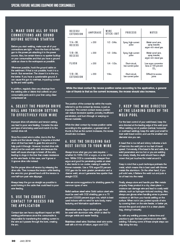
While the ideal contact tip recess position varies according to the application, a general
rule of thumb is that as the current increases, the recess should also increase.